
| Title: | Piping and Valves | Doc. No. | L-001 | Annex | D | VSM | |
| Project: NORSOK | Company: | Rev.Date: | 20.09.99 | Rev: | 3 | ||
![]()
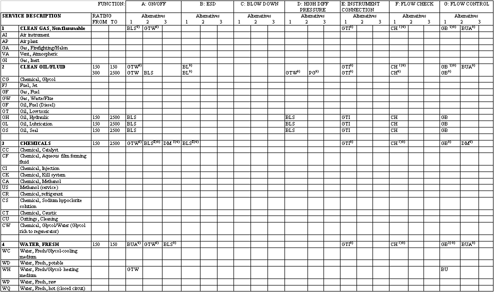
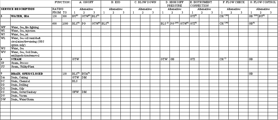
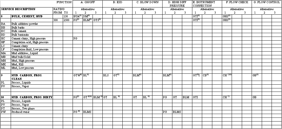
The valve selection manual (VSM) in Table D.1 below, gives recommendation to valve types which are suitable for different service catergories. Each service categories represent a group of systems with similar characteristics.
For small bore valves listed both with welding and flanged end, the flanged end type should be used in areas where hot work should be cept to a minimum. Flanged valves are in general the preferred solution, especially where the valve is subject to frequent maintenance.
Valve listed with one end threaded and one end welded are specified to provide interface to instrument connection. When ball valve is selected the reduced bore type shall be prefered unless full bore is required. For hydrocarbon service with strict requirement to safety, valve of welded end type should be evaluated. (eg. To reduce extent of classified area).
For services with several valve alternatives listed, the project shall evaluate type of valve most feasible based on:
· Operation experience
· Overall cost (Life cycle cost (LCC) inclusive project and operating phase.)
· Overall design requirements
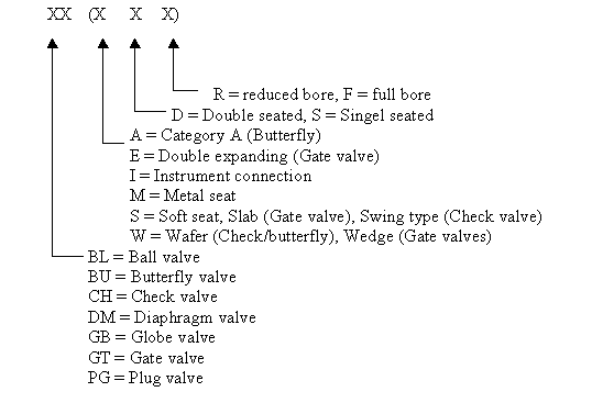
The valve types is specified by a text code, the text code consist of munimum two letters (eg. BL). If the texts code consist of more than two letters the valve trim or trimmaterial is specified (eg. BLMS).
The characters in the VSM manual has the following meaning:

Some valve types are limited in use for certain service condition. Such limitations are given as valve selection notes to each service category.
When printing the tables, use these links and print with landscape orientation.
Table 1
Table 2
Table 3


| 1 | Wafer type check valve (CHW) shall be used unless othervise required for size above 1.5" |
| 2 | For dimensions above 4" the butterfly valve could be used as alternativ for moderate flow control |
| 3 | If diferential pressure exceed 30 Barg use GTW, see function D |
| 4 | Other valves than specified can be used after location of sand removal. |
| 5 | Diaphragme valve shall only be used in CL150 |
| 6 | Slab gate to be selected for wells with sand production Double expanding gate valve to be selected for reservoir scale production. Reversed portvalves to be used if fail closed mode is required. |
| 8 | Seal material suitable for the service which gives no lea |
| 9 | Limitations in the temperature area for the valves are not considered. |
| 10 | Limitations of soft seat materials in valves, see general part of Annex D, section D4. |
D.5 Guide to selection of soft seal materials.
The purpose of this section is to give a guide for selection of soft seat materials for valves.
Acceptable materials for standard NORSOK valves are referred to on each VDS as reference to EDS NSM1 (Norsok seal material) and NSS1 (Norsok soft seat materials).
This guide also includes materials that are not acceptable/interchangeable with the specified materials. However, if process conditions are within the limitations of these materials, the purchaser is allowed to provide new VDS`s for "special purpose" within the rules of numbering given in section 5, Project requirements and information.
Table D.2
Seal materials
| Seal type | Material | MDS | Applicable pressure classes & temperature range. | Additional information/ limitations |
| O-ring | Hydrogenated nitrile 1) (HNBR) (36 40% Acrylonitrile) |
MDS P11 | 150-900 lb./ -46 to 150° C. 1500 -2500 lb./ 46 to 120° C Note that the mechanical properties of the material is reduced at increasing temperature. This must be reflected in the valve design by use of i.e. back up ring. |
Maximum temperature range: -46 to 150 ° C. Maximum 5 vol % H2S in gas phase. Not to be exposed to: Highly aromatic oils such as xylene and toluene, zinc bromide brines, ketones, acetone, strong acids, esters and halogenated hydrocarbons. Max. continuous operating temperature for medium including steam and hot water is below 120°C for design life exceeding 10 years. Exposure to temperatures below -20°C only for short durations and then full sealing capability during valve operation can not be expected. |
| O-ring | Fluorcarbon-terpolymer 1) (FKM Viton B type) | MDS P12 | 150-900 lb./ -46 to 150° C. 1500- 2500 lb./ 46 to 120° C Note that the mechanical properties of the material are reduced at increasing temperature. This must be reflected in the valve design by use of i.e. back up ring. |
Maximum temperature range: -46 to 210 ° C. Maximum 5 vol % H2S in gas phase. Max. continuous operating temperature for medium including steam and hot water is below 100°C for design life exceeding 10 years. Exposure to temperatures below -10°C only for short durations and then full sealing capability during valve operation can not be expected. Not to be exposed to amine based corrosion inhibitors (amines), ketones, esters, concentrated hydrofluoric acid, low molecular weight organic acids such as formic and acetic acid or caustic solutions. Exposure to pure methanol must be limited in duration. |
| O-ring | Fluorcarbon low temperature terpolymer2) (FKM -Viton GLT type) |
MDS P13 | Not applicable for standard valves. Note that the mechanical properties of the material are reduced at increasing temperature. This must be reflected in the valve design by use of i.e. back up ring. |
Temperature limitation: -46 to 200° C. Not to be used in gas service or gas containing fluids where rapid pressure reduction damage is a possibility. Generally reduced chemical resistance compared to MDS P12 (FKM-viton B type.), especially against hot water, amines and methanol. Maximum operating temperature for medium including steam and hot water is below 90° C for design life exceeding 10 years. Exposure to temperatures below -30°C only for short durations and then full sealing capability during valve operation can not be expected. Not to be exposed to methanol, ethanol, amine based corrosion inhibitors (amines), ketones, esters, concentrated hydrofluoric acid, low molecular weight organic acids such as formic and acetic acid or caustic solutions. |
| O-ring | Nitrile, NBR 2) | MDS P14 | Not applicable for standard valves. | Temperature limitation: -20 to 100° C. Not to be used in gas service or gas containing fluids where rapid pressure reduction damage is a possibility. Maximum operating temperature for medium including steam and hot water is below 80° C for design life exceeding 10 years. Not to be exposed to H2S, zinc bromides, highly aromatic oils such as xylene and toulene, ketones, acetones, strong acids, esters and halogenated hydrocarbons. Exposure to methanol must be limited in duration. |
| Lip seal | PTFE | MDS P22 | 150-2500 lb./ -46 to 200° C. | Temperature limitation: -46 to 200° C The PTFE lip-seals can be used for all pressure classes provided the design and material selection is made accordingly. For selection of back-up ring material reference is made to the requirements for PEEK material below. Metallic spring material shall be equal to or better then UNS R 30003 (Elgiloy). If energised by O-ring, limitations for above listed alternative materials apply. |
| Back-up rings | PEEK | MDS P21 | 150-2500 lb./ -46 to 250° C. | Temperature limitation: -100 to 250° C Not to be exposed to hot concentrated inorganic acids. |
| Back-up rings | PTFE based | MDS P22 | 150-2500 lb./ -46 to 200° C. | Temperature limitation: -190 to 200° C Back-up rings made of filled PTFE may be considered based on pressure class considerations, temperature, seal design, seal gap and qualification tests. |
| Packed gland | Expanded graphite | | 150-25000 lb./ -46 to 200° C. | Temperature limitation: -46 to 200° C Not less than 98% purity. |
| | PTFE based | MDS P22 | 150-2500 lb./ -46 to 200° C. | Temperature limitation: -46 to 200° C |
Table D.3
Seat materials
| Material | MDS | Applicable pressure classes & temperature range. | Additional information/ limitations |
| Polytetrafluoroethylene (PTFE) | P 22 | 150-300 lb./ -46 to 150° C. | Temperature limitation: -190 to 200° C. Mechanical properties of the material are reduced by increasing temperature. |
| Polyetheretherketone (PEEK) | P 21 | 150-900 lb./ -46 to 150° C. 1500- 2500 lb./ 46 to 120° C |
Temperature limitation: -100 to 250° C. Not to be exposed to hot concentrated inorganic acids. Mechanical properties of the material are reduced by increasing temperature. |
| Polyetheretherketone (PEEK) with 10-20% Polytetrafluoroethylene (PTFE) | P-23 | 150-900 lb./ -46 to 150° C. | Temperature limitation: -100 to 200° C. Not to be exposed to hot concentrated inorganic acids. Mechanical properties of the material are reduced by increasing temperature. |
| Ethylene-chloro-trifluoro-ethylene copolymer (ECTFE) | | 150-900 lb./ -46 to 150° C. | Temperature limitation: -70 to 150° C. Not to be exposed to methanol above 50 °C or aromatic hydrocarbons such as xylene above 75 °C. Further, not to be exposed to strong organic amines above 23°C. A detailed material data sheet must be written before a purchase of the material can be made. Mechanical properties of the material are reduced by increasing temperature. |
| Polyamide 11/ 12 (PA 11/ 12) (Nylon 11/ 12) | | Not applicable for standard valves. See table D.3.1 below for guidance on expected service life at different operating conditions. |
Notes to table below: The water content creating the degradation of the Polyamide materials is defined as 80 % of water vapour saturation in gas and 0.1-0.2 wt. % water in any liquid. Exposure to water with lower pH or to acids reduces the service life further. Design temperature range for continuos service (25 years) with methanol present: -50°C to 37°C. Other polyamide qualities have different behaviour compared to PA 11 and 12, but the general resistance against water and methanol is lower. If used, the temperature limits must be established by long term testing. |
Table D.3.1:
Service limitations for Polyamide/ Nylon in exposure to gas or fluids containing water is tabled below:
| Service life (years) | pH 5 in water phase | pH 7 in water phase |
| 5 10 20 25 |
- 50 to 72 ° C - 50 to 65 ° C - 50 to 60 ° C - 50 to 57 ° C |
- 50 to 77 ° C - 50 to 70 ° C - 50 to 65 ° C - 50 to 62 ° C |
Notes for table D2 and D3.